Monday, October 05, 2009

A ForceField Diagram

The Design Rationale Diagram I discussed in my previous post is hardly complete, and it could be vastly improved by asking slightly different questions, leading to different decision paths. Still, it's a reasonable first-cut attempt to model the decision process. It can be used to communicate the reasoning behind a specific decision, in a specific context.

That, however, is not the way I really think. Sure, I can rationalize things that way, but it's not the way I store, recall, organize information inside my head. It's not the way I see the decision space.
In the end, software design is about things going together and things staying apart, at all the granularity levels (see also my post on partitioning).
As I progress in my understanding of forces, I tend to form clusters. Clusters are born out of attraction and rejection inside the decision space. I've found that thinking this way helps me reach a better understanding of my design instinct, and to communicate my thoughts more clearly.

Now, although I've been thinking about this for long while (not full-time, lucky me :-), I can't say I have found the perfect representation. The decision space in inherently multi-dimensional, and I always end up needing more dimensions that I can fit either in 2D or 3D. Over time, I tried several notations, inventing things from scratch or borrowing from other domains. Most were dead ends. In the end, I've chosen (so far :-) a very simple representation, based on just 3 concepts (possibly 4 or 5).

- nodes
Nodes represent information, which is our material. Information has fractal nature, and I don't bother if I'm mixing up levels. Therefore, a node may represent a business goal, or the adoption of a tool or library, or a nonfunctional requirement, or a specific component, class, function. While most methods are based on a strict separation of concepts, I find that very limiting.

- an attraction relationship
Nodes can attract each other. For instance, a node labeled "reliable" may attract a node labeled "redundant" when reasoning about the large display problem. I just connect the two nodes using a thick line with little "hands" on the ends. I place attracted nodes close to each other.

- a rejection relationship
Nodes can reject each other. For instance, stateful most clearly reject stateless :-). Some technology might be at odd with another. A subsystem must not depend on another. And so on. Nodes that reject each other are placed at some distance.

It's all very simple and unsophisticated. Here is an example based on the large display problem, inspired by the discussion on design rationale:


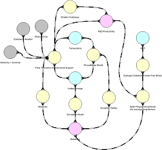
and here are two diagrams I've used in real-world projects recently, scaled down to protect the innocent:


The relationship between a node, a cluster, and an Alexandrian center is better left for another time. Still, a node in one diagram may represent an entire cluster, or an entire diagram. Right now I'm tempted to use a slightly different symbol (which would be the fourth) to represent "expandable" nodes, although I'm really trying to keep symbols to a bare minimum. I'm also using colors, but so far in a very informal way.

As simple as it is, I've found this diagram to be very effective as a reasoning device, while too many diagrams end up being mere documentation devices. I can sit in front of my (large :-) screen, think and draw, and the drawing helps me focus. I can draw this on a whiteboard in a meeting, and everyone get up to speed very quickly on what I'm doing.

This, however, is just half the story. We can surely work with informal concepts and diagrams, and that's fine, but what I'm trying to do is to add precision to the diagram. Precision is often confused with details, like "a class diagram is more precise if you show all the parameters and types". I'm not looking for that kind of "precision". Actually, I don't want this diagram to be redundant with code at all; we already have many code-like diagrams, and they all get down the same roads (generate code from diagrams or generate diagrams from code). I want a reasoning device: when I want to code, I'm comfortable with code :-).

I mostly want to add precision about relationships. Why, for instance, is there an attraction between Slow Client and Stateful? Informally, because if we have a stateful system, the slow client can poll on its own terms, or alternatively, because the client may use a sophisticated subscription based on the previous state. Those options, by the way, could be represented on the forcefield diagram itself (adding more nodes, or a nested diagram); but that's still the "informal" reasoning. Can we make it any more formal, precise, grounded on sound principles?

This is where the ongoing work on concepts like gravity, frequency, and so on kicks in. Slow Client and Stateful are attracted because on a finer granularity (another, perhaps better, diagram) "Slow Client" means a publisher and a subscriber operating at different frequencies, and a stateful repository is a well-known strategy (a pattern!) to provide Isolation between systems operating at different frequencies (together with synchronization or transactions).

Now, I haven't introduced the concept of Isolation yet (though I mentioned something on my Facebook page :-), so this is sort of a spoiler :-)), but in the end I hope to come up with a simple reasoning system, where you can start with informal concepts and refine nodes and forces until you reach the "universal", fractal forces I'm discussing in the "Notes on Software Design" posts. That would give a solid ground to the entire diagram.

A final note on the forcefield diagram: at this stage, I'm just using Visio, or more exactly, I'm abusing some stencils in the Visio library. I wanted something relatively organic, mindmap-like. Maybe one day I'll move back to some 3D ideas (molecular structures come to mind), but I've yet to see how this scales to newer concepts, larger problems, and so on. If you want to play with it, I can send you the VSS file with the stencils.

Ok, I'll get back to Frequency (and Interference and Isolation and more :-) soon. Before that, however, I'd like to take a diversion on the Dependency Structure Matrix. See ya!

Monday, August 31, 2009

Representing Design Rationale Inside Activity Diagrams

Design is about making choices. We often do so on the fly, leaning on experience and intuition, by talking about the problem with colleagues, or borrowing from literature (e.g. patterns). We also make some choice by habit, which is a different form of experience, one that has higher risk of becoming disconnected with the real problem.
Most of this process is tacit, and even when we discuss choices openly, it doesn't get recorded. Sometimes, a list of pros/cons is made when there is some disagreement about the best option.

This all works well when the problem is simple, but sometimes even experienced designers feel like they're not grasping the essential issues, that something has not yet been found, named, disentangled. This is when having yet one more tool can prove useful.
Now, I don't usually go through the effort to model and transcribe the rationale behind each and every design choice I make. It could be interesting, also from a pedagogical point of view, but it would take a lot of time and would probably disrupt my thought processes. However, when the issues are particularly thorny/unclear, or when there is a large disagreement on the best choice (or even on the goals and criteria), I've found that getting design rationale out of our individual heads and talk on a shared representation can move things a little forward.

Over the years, I've tried out a number of tools, approaches, and so on; lately, I've tried using Activity Diagrams in a rather unorthodox way, to represent my reasoning about design, not design itself. The idea is not to encode your decisions ex-post, but ex-ante, while you're thinking (that is, while they're still options, not decisions). Also, the diagram must be considered quite fluid, as it shows our current understanding, and we're building the diagram to improve our understanding.

Enough talk, let's see a realistic example. I'll refer to the Large Display problem I discussed a few months ago. Actually, I'll just cover the initial choice between using a real-time database or an IPC/messaging system. It's gonna be quite a mouthful anyway!

To start, I'll have to draw a line between a messaging system and a RTDB, and that in itself is not easy. I'll go for a very simple distinction, because my goal here is not really to talk about RTDBs, but about design rationale (the usual "look at the moon, not at the finger" concept).
So, consider a control system that reads some data from the field and then needs to publish those data for other processes. It could just send data through a messaging (publish/subscribe) system. Here I define a messaging system as stateless, meaning it simply keeps track of subscriptions, and sends everything that is published to the subscribers (according to some criteria, like message type or tag). It does not keep an history, or a snapshot of what has been last sent. Therefore, it cannot apply some filters, like "notify me only if the difference between the previous value and the current value is above a threshold" because the previous value is just not stored. Also, when a subscriber is started, it cannot get the current snapshot of the system, because it is not there: it will have to wait for messages to come, incrementally. Shortly stated, a RTDB will keep a snapshot of the system, and well, you can figure out the difference. Of course, a RTDB is also more complex.

So, how do we choose between a messaging system and a RTDB? We may write down a long list of pro/cons, but that's really unstructured, and that's not the way our brain works. To provide more structure, I use an Activity Diagram with orthogonal swimlanes (all the following pictures are taken from Star UML, a free tool that is rather fast and unobtrusive).
The vertical swimlanes are flexible: they represent the main concerns. The horizontal swimlanes are fixed: they provide structure.


For the Large Display problems, we could start with a few main concerns like performance, reliability, cost, and so on. We just drop the names on the vertical swimlanes. My template is then partitioned in 3 horizontal bands: the root question, the reasoning, the outcome. Everything inside is dynamic, and changes as we understand more: even the root questions may change, as we discover larger or smaller, independent problems. Sometimes, even the main concerns change, as we discover options or issues we didn't consider before.

We can focus on just one concern right now, let's say performance (don't we all like performance? :-). A first-cut, interesting top-level question could be: is the published data rate high or low? If the rate is low and we have no persistent state, when you turn on the large display you see nothing: you have to wait till some data gets published. On the other hand, if the rate is high, it may even overwhelm the display system: there is little need to refresh a value a thousand times per second. That actually depends on the display: if it's a real-time plot, you may want a high refresh rate too.

Ok, we could start modeling this part of our reasoning using the familiar activity diagram symbols. Actually, since most of the nodes here would be decision nodes, I just omit the diamond and use an activity node with multiple outgoing paths to show choices.


Note: The empty boxes are just placeholders for some later reasoning. It's just laziness on my side :-) and they wouldn't appear in a real diagram.

Now, this seems just like a decision tree, but it's slightly different. First, it's a decision graph: common choices between paths are shared, and this is a precious information because it shows crucial choices (more on this later). Second, it's a multifaceted graph: every vertical swimlane shows a facet of a more complex reasoning; for instance, what is good for performance might not be good for reliability or cost.

Let's try to move ahead a little. When the incoming data rate is higher than what [most] clients need, we have basically two choices:
1) smarter subscriptions; they could still be rather dumb, like "no more than 3 times per second" or much smarter like "when relative change is higher than 5%, but no more than 5 times per second". Note that the latter is more suited to a RTDB than to a stateless messaging system.
2) change paradigm and move to client-initiated polling. The clients will ask for data with their own timing. Of course, at this point we give up the possibility of not asking for data if the value has not changed. Anyway, this again requires some kind of stateful middleware; a messaging system won't do.
When data rate is low, but high startup time for clients is not an option, we can't wait for data to come: we have to poll, at least at startup. So, polling can solve two problems, of course at expense of bandwidth if it is the only available option.


While drawing this, we may come to the conclusion that we need to ask better questions: are we building a publisher-driven or a client-driven system? If it's client-driven, it cannot be stateless! What do we really know about clients? How many there will be? What about publishers? What is the typical data rate and configuration? What are we aiming for? Do we need to narrow the expectations? This might change the top question (client Vs. publisher driven) or even some concern. That's fine, it means the technique is working :-) and that it's helping us thinking.

Now, it would take quite a lot of time to explore all the facets of even a simple system like this. Actually, most people won't even do it in real life: they will fall in love with one idea, spend most of their time preaching and rationalizing about the virtues of their idea, and never really take the time to go through this kind of process. Still, trying to work out the "Reliability" swimlane would prove interesting. For instance, a common technique to achieve reliability is redundancy. Redundancy is much easier for a stateless system. Redundancy is easier when clients don't have to subscribe at all, but can simply poll. And so on. If you have some spare time, you may want to give it a try.

The notation I use is quite informal. I could improve that easily: UML is fairly flexible; so far I didn't, because people can grasp it anyway, even when I drop in the < < or > > to represent options or when I have just one arrow coming out, meaning that I've just decomposed a choice and a consequence. It's just a reasoning workflow, and I haven't felt the need to make it any more precise than that.

Back to the forcefield: the rationale is not the forcefield. The rationale, however, is talking about forces and centers. Outcomes (messaging and RTDB) are centers. Main choices, like "client driven" or "stateless", are again centers. Those centers are attracting or rejecting each other. This is the forcefield. This is closer to the way I think in the back of my mind, how I "see" the system, how I keep options open. Now, I just need a way to show this. That's for my next post :-).

Tuesday, June 09, 2009

Design Rationale

In the past few weeks I've taken a little time to write down more about the concept of frequency; while doing so, I realized I had to explore the concept of forcefield better, and while doing so (yeap :-)) I realized there was a rather large overlap between the notion of forcefield and the notion of design rationale.

Design rationale extends beyond software engineering, and aims to capture design decisions and the reasoning behind those decisions. Now, design decisions are (ideally) taken as trade-offs between several competing forces. Those forces creates the forcefield, hence the large overlap between the two subjects.

The concept of design rationale has been around for quite a few years, but I haven't seen much progress either in tools or notations. Most often, tools fall into the “rationalize after the fact” family, while I'm more interested in reasoning tools and notations, that would help me (as a designer) get a better picture about my own thoughts while I'm thinking. That resonates with the concept of reflection in action that I've discussed in Listen to Your Tools and Materials a few years ago.

So, as I was reading a recent issue of IEEE Software (March/April 2009), I found a list of recent (and not so recent) tools dealing with design rationale in a paper by Philippe Kruchten, Rafael Capilla, Juan Carlos Dueñas (The Decision View’s Role in Software Architecture Practice), and I decided to take a quick ride. Here is a very quick summary of what I've found.

Seurat
Seurat (see also the PDF tutorial on the same website) is based on a very powerful language / model, but the tool (as implemented) is very limiting. It's based on a tree structure, which makes for a nice todo list, but makes visual reasoning almost impossible. Actually, in the past I've investigated on using the tree format myself (and while doing so, I discovered others have done the same: see for instance the Reasoning Tree pattern), but restricting visualization to (hyperlinked) nodes in a tree just does not work when you're facing difficult problems.

Sysiphus
Sysiphus seems to have recently morphed into another tool (UniCase), but from the demo of UniCase it's hard to appreciate any special support for design rationale (so far).

AREL
(see also some papers from Antony Tang on the same page; Antony also had an excellent paper on AREL in the same issue of IEEE Software)
AREL is integrated with Enterprise Architect. Integration with existing case tools (either commercial or free) seems quite a good idea to me. AREL uses a class diagram (through a UML profile) to model design rationale, so it's not limited to a tree format. Still, I've found the results rather hard to read. It seems more like a tool to give structure to design knowledge than a tool to reason about design. As I go through the examples, I have to study the diagram; it doesn't just talk back to me. I have to click around and look at other artifacts. The reasoning is not in the diagram, it's only accessible through the diagram.

PAKME
Honestly, PAKME seems more like an exercise in building a web-based collaboration tool for software development than a serious attempt at providing a useful / usable tool to record design rationale. It does little more than organize artifacts, and it requires so many clicks / page refresh to get anything done that I doubt a professional designer could ever use it (sorry guys).

ADDSS
ADDSS is very much like PAKME, although it adds a useful Patterns section. It's so far from what I consider a useful design tool (see my paper above for more) that I can't really think of using it (sorry, again).

Knowledge Architect
Again, a tool with some good ideas (like Word integration) but far from what I'm looking for. It's fine to create a structured design document, but not to reason about difficult design problems.

In the end, it seems like most of those tools suffer from the same problems:
- The research is good; a nice metamodel is built, some of the problems faced by professional designers seem to be well understood.
- The tool does little more than organize knowledge, would get in the way of the designer thinking about thorny issues, does not help through visualization, and is at best useful at the end of the design process, possibly to fake some rationality, a-la Parnas/Clements.

That said, AREL is probably the most promising tool of the pack, but in the end I've being doing pretty much the same for years now, using (well, abusing :-) plain old use case diagrams to model goals and issues, with a few ideas taken from KAOS and the like.

Recently, I began experimenting with another standard UML diagram (the activity diagram) to model some portion of design reasoning. I'll show an example in my next post, and then show how we can change our perspective and move from design reasoning to the forcefield.

Sunday, April 26, 2009

Bad Luck, or "fighting the forcefield"

In my previous post, I used the expression "fighting the forcefield". This might be a somewhat uncommon terminology, but I used it to describe a very familiar situation: actually, I see people fighting the forcefield all the time.

Look at any troubled project, and you'll see people who made some wrong decision early on, and then stood by it, digging and digging. Of course, any decision may turn out to be wrong. Software development is a knowledge acquisition process. We often take decisions without knowing all the details; if we didn't, we would never get anything done (see analysis paralysis for more). Experience should mitigate the number of wrong decisions, but there are going to be mistakes anyway; we should be able to recognize them quickly, backtrack, and take another way.

Experience should also bring us in closer contact with the forcefield. Experienced designers don't need to go through each and every excruciating detail before they can take a decision. As I said earlier, we can almost feel, or see the forcefield, and take decisions based on a relatively small number of prevailing forces (yes, I dare to consider myself an experienced designer :-).
This process is largely unconscious, and sometimes it's hard to rationalize all the internal reasoning; in many cases, people expect very argumentative explanations, while all we have to offer on the fly is aesthetics. Indeed, I'm often very informal when I design; I tend to use colorful expressions like "oh, that sucks", or "that brings bad luck" to indicate a flaw, and so on.

Recently, I've found myself saying that "bad luck" thing twice, while reviewing the design of two very different systems (a business system and a reactive system), for two different clients.
I noticed a pattern: in both cases, there was a single entity (a database table, a in-memory structure) storing data with very different timing/life requirements. In both cases, my clients were a little puzzled, as they thought those data belonged together (we can recognize gravity at play here).
Most naturally, they asked me why I would keep the data apart. Time to rationalize :-), once again.

Had they all been more familiar with my blog, I would have pointed to my recent post on multiplicity. After all, data with very different update frequency (like: the calibration data for a sensor, and the most recent sample) have a different fourth-dimensional multiplicity. Sure, at any given point in time, a sensor has one most recent sample and one set of calibration data; therefore, in a static view we'll have multiplicity 1 for both, suggesting we can keep the two of them together. But bring in the fourth dimension (time) and you'll see an entirely different picture: they have a completely different historical multiplicity.

Different update frequencies also hint at the fact that data is changing under different forces. By keeping together things that are influenced by more than one force, we expose them to both. More on this another time.

Hard-core programmers may want more than that. They may ask for more familiar reasons not to put data with different update frequencies in the same table or structure. Here are a few:

- In a multi-threaded software, in-memory structures requires locking. If your structure contains data that is seldom updated, that means it's being read more than written: if it's seldom read and seldom written, why keep it around at all?
Unfortunately, the high-frequency data is written quite often. Therefore, either we accept to slow down everything using a simple mutex, or we aim for higher performances through a more complex locking mechanism (reader/writer lock), which may or may not work, depending on the exact read/write pattern. Separate structures can adopt a simpler locking mechanism, as one is being mostly read, the other mostly written; even if you go with a R/W lock, here it's almost guaranteed to have good performance.

- Even on a database, high-frequency writes may stall low-frequency reads. You even risk a lock escalation from record to table. Then you either go with dirty reads (betting on your good luck) or you just move the data in another table, where it belongs.

- If you decide to cache database data to improve performances, you'll have to choose between a larger cache with the same structure of the database (with low frequency data too) or a smaller and more efficient cache with just the high-frequency data (therefore revealing once more that those data do not belong together).

- And so on: I encourage you to find more reasons!

In most cases, I tend to avoid this kind of problems instinctively: this is what I really call experience. Indeed, Donald Schön reminds us that good design is not for everyone, and that you have to develop your own sense of aesthetics (see "Reflective Conversation with Materials. An interview with Donald Schön by John Bennett", in Bringing Design To Software, Addison-Wesley, 1996). Aesthetics may not sound too technical, but consider it a shortcut for: you have to develop your own ability to perceive the forcefield, and instinctively know what is wrong (misaligned) and right (aligned).

Ok, next time I'll get back to the notion of multiplicity. Actually, although I've initially chosen "multiplicity" because of its familiarity, I'm beginning to think that the whole notion of fourth-dimensional multiplicity, which is indeed quite important, might be confusing for some. I'm therefore looking for a better term, which can clearly convey both the traditional ("static") and the extended (fourth-dimensional, historical, etc) meaning. Any good idea? Say it here, or drop me an email!

Monday, March 30, 2009

Notes on Software Design, Chapter 5: Multiplicity

Gravity, as we have seen, provides a least resistance path, leading to monolithic software. If gravity was the only force at play, all software would be a monolithic blob. That being not the case, there must be other forces at play. Pervasive, primitive forces just like gravity, setting up a different forcefield, so that it's more convenient to keep things apart.

Consider an amateur programmer, writing a simple program to keep track of his numerous books. He starts with a database-centric approach, and without much knowledge of conceptual modeling, he jumps into creating tables. He creates a Book table, and adds a few fields:
AuthorFirstName, AuthorLastName, Title, Publisher, ISBN, …
It doesn't take much for him to realize that an author could be present several times in his database. He may begin to realize that he could perhaps add an Author table and move AuthorFirstName and AuthorLastName to that table.

Why? He doesn't know squat about database normalization. It's just a simple matter of multiplicity. One author - many books. Different multiplicity suggests to keep things apart. It is quite a good suggestion, as different multiplicity basically requires different gravitational centers, lest we end up with an unfavorable forcefield.
Consider what happens when our amateur programmer discovers he wants to add more biographical data about authors. Without an Author table, there is not any good gravitational center that could possibly attract those data. There is only the Book table, so there they go - adding more data redundancy.

Our amateur programmer, however, might not be so eager to give in. A single table is easier to manage. No foreign keys, no referential integrity, no nothing. It's just simpler, and he doesn't live in the future. He wants to do the simplest thing that could possibly work, so he keeps the Author fields inside the Book table.

He doesn't need much more, however, to realize that many books have more than one author. One book - many authors. That's a different forcefield again, with a many-to-many relationship. Now, our amateur is rather stubborn. He wants to keep things inside a single table anyway. So he goes on and adds more fields:

AuthorFirstName1, AuthorLastName1, AuthorFirstName2, AuthorLastName2, AuthorFirstName3, AuthorLastName3, Title, Publisher, ISBN, …

Of course, at this point he can basically feel he's no longer going along the path of least resistance. Actually, he's fighting the forcefield. Sure, gravity wants him to keep things together, but multiplicity doesn't. The form he's trying to give to the Book table is not in frictionless contact with the forcefield. The forcefield wants Book and Author to stay on their own.

Multiplicity is the primordial force that keeps [software] things apart. It shouldn't come as a surprise, then, that a great emphasis is given to multiplicity in the Entity-Relationship model and also in the static view of OO models (class diagram).
Multiplicity, however, goes much deeper than that. Reusability is a special case of multiplicity. What? :-). Well, it that sounds odd, you're not thinking fourth dimensionally (as Doc said in "Back to the future").

Consider a different problem, at a different granularity. Our amateur programmer is writing another small application, to keep track of who has borrowed some of his precious books. He's doing the simplest thing again, so he's basically going GUI-centered, and he's putting all the business logic inside the form itself. When you click on "Ok", the form will validate data and store a record into some table. The form requires, among other things, a phone number, which must be validated. It's the only place where he has to validate a phone number, so he puts the validation logic right inside the OnOk method generously provided by his RAD tool.

What's wrong? Apparently, there is no multiplicity at play here. There is one function, where he's doing two distinct things (validation and insertion), and inside validation he's doing different things, but each one is intended to validate one field, so it wouldn't pay to move the field validation logic elsewhere. Gravity keeps things together.

Multiplicity is hidden in the fourth dimension: time. Reusability means being able to take something you have already written (in the past) and use it again, unchanged, in the future. It means you have multiple callers, just not at the same time. If you think fourth dimensionally, multiplicity comes out quite clearly.

Multiplicity is an interesting force, one we need to be very familiar with. It will take a few posts to give it justice. Right now, it's time for me to put my running shoes on and hit the road :-). Still, here are a few pointers to some important issues that I'm going to cover in the next weeks (or months :-)

The fractal nature of multiplicity
Maintainability
Scalability
Conway's Law
Tools and Languages - lowering costs
Good questions to ask while doing analysis and design.
Is multiplicity stronger than gravity?
Examples from patterns. On truly understanding Abstract Factory.
N-degrees of separation.
Interfaces and Multiplicity - what is separation, anyway?
Cross-cutting concerns.
Down-to-earth guidelines.
The Display problem, once again.

Sunday, February 22, 2009

Notes on Software Design, Chapter 4: Gravity and Architecture

In my previous posts, I described gravity and inertia. At first, gravity may seem to have a negative connotation, like a force we constantly have to fight. In a sense, that's true; in a sense, it's also true for its physical counterpart: every day, we spend a lot of energy fighting earth gravity. However, without gravity, like as we know it would never exist. There is always a bright side :-).

In the software realm, gravity can be exploited by setting up a favorable force field. Remember that gravity is a rather dumb :-) force, merely attracting things. Therefore, if we come up with the right gravitational centers early on, they will keep attracting the right things. This is the role of architecture: to provide an initial, balanced set of centers.

Consider the little thorny problem I described back in October. Introducing Stage 1, I said: "the critical choice [...] was to choose where to put the display logic: in the existing process, in a new process connected via IPC, in a new process connected to a [RT] database".
We can now review that decision within the framework of gravitational centers.

Adding the display logic into the existing process is the path of least resistance: we have only one process, and gravity is pulling new code into that process. Where is the downside? A bloated process, sure, but also the practical impossibility of sharing the display logic with other processes.
Reuse requires separation. This, however, is just the tip of the iceberg: reuse is just an instance of a much more general force, which I'll cover in the forthcoming posts.

Moving the display logic inside a separate component is a necessary step toward [independent] reusability, and also toward the rarely understood concept of a scaled-down architecture.
A frequently quoted paper from David Parnas (one of the most gifted software designers of all times) is properly titled "Designing Software for Ease of Extension and Contraction" (IEEE Transactions on Software Engineering, Vol. 5 No. 2, March 1979). Somehow, people often forget the contraction part.
Indeed, I've often seen systems where the only chance to provide a scaled-down version to customers is to hide the portion of user interface that is exposing the "optional" functionality, often with questionable aesthetics, and always with more trouble than one could possibly want.

Note how, once we have a separate module for display, new display models are naturally attracted into that module, leaving the acquisition system alone. This is gravity working for us, not against us, because we have provided the right center. That's also the bright side of the thorny problem, exactly because (at that point, that is, stage 2) we [still] have the right centers.

Is the choice of using an RTDB to further decouple the data acquisition system and the display system any better than having just two layers?
I encourage you to think about it: it is not necessarily trivial to undestand what is going on at the forcefield level. Sure, the RTDB becomes a new gravitational center, but is a 3-pole system any better in this case? Why? I'll get back to this in my next post.

Architecture and Gravity
Within the right architecture, features are naturally attracted to the "best" gravitational center.
The "right" architecture, therefore, must provide the right gravitational centers, so that features are naturally attracted to the right place, where (if necessary) they will be kept apart from other features at a finer granularity level, through careful design and/or careful refactoring.
Therefore, the right architeture is not just helping us cope with gravity: it's helping us exploit gravity to our own advantage.

The wrong architecture, however, will often conjure with gravity to preserve itself.
As part of my consulting activity, I’ve seen several systems where the initial partitioning of responsibility wasn’t right. The development team didn’t have enough experience (with software design and/or with the problem domain) to find out the core concepts, the core issues, the core centers.
The system was partitioned along the wrong lines, and as mass increased, gravity kicked in. The system grew with the wrong form, which was not in frictionless contact with the context.
At some point, people considered refactoring, but it was too costly, because mass brings Inertia, and inertia affects any attempt to change direction. Inertia keeps a bad system in a bad state. In a properly partitioned system, instead, we have many options for change: small subsystems won’t put up much of a fight. That’s the dream behind the SOA concept.
I already said this, but is worth repeating: gravity is working at all granularity levels, from distributed computing down to the smallest function. That's why we have to keep both design and code constantly clean. Architecture alone is not enough. Good programmers are always essential for quality development.

What about patterns? Patterns can lower the amount of energy we have to spend to create the right architecture. Of course, they can do so because someone else spent some energy re-discovering good ideas, cleaning them up, going through shepherding and publishing, and because we spent some time learning about them. That said, patterns often provide an initial set of centers, balancing out some forces (not restricted to gravity).
Of course, we can't just throw patterns against a problem: the form must be in effortless contact with the real problem we're facing. I've seen too many good-intentioned (and not so experienced :-) software designers start with patterns. But we have to understand forces first, and adopt the right patterns later.

Enough with mass and gravity. Next time, we're gonna talk about another primordial force, pushing things apart.

See you soon, I hope!

Wednesday, January 14, 2009

Notes on Software Design, Chapter 3: Mass, Gravity and Inertia

I thought I could discuss the whole concept of Gravity and its implications in 2 or 3 (long) posts. While writing, I realized I'll need at least 4 or 5. So, this time I'll talk a little about how we can cope with gravity, and about the concept of Inertia. Next time, I'll discuss how we can exploit gravity, and why (despite the obvious cost) it is important that we do not surrender to (or ignore) gravity.

How do we cope with gravity? Needless to say, we have to spend some energy to move away from the amorphous big blob. As usual, we can also borrow some of that energy from someone (or something) else. Here are a few well-proven ideas:

- Architecture. I used to define architecture as "an overall structure, providing a natural place for features and concepts". I could now say that architecture must provide the right centers, or (from the viewpoint of mass and gravity) the right gravitational centers, so that the system can grow harmoniously. The right architecture is also the key to exploit gravity. More about this (and about the role of design patterns) next time.

- Refactoring. While architecture requires some kind of upfront investment, refactoring fights gravity in a more piecemeal, continuous fashion.
Although Refactoring and Emergent Design are often seen as the arch-enemies of Architecture, they are not. Experienced developers know that both are needed, as they work at different scales.
No amount of architecture, for instance, will ever prevent small-scale gravity to attract more code into existing functions. When we add a new feature (maybe under a tight deadline) gravity suggests to add that feature in place, often without even breaking the smallest separation unit – the function.
Conversely, gravity (and even more so Inertia) does not allow refactoring to scale economically beyond some (hard to identify) threshold.

- Measurement and Correction. While refactoring is often performed on-the-fly by programmers, fixing bad smells as they go, we can also use automatic tools to help us keep the code within some quality bounds. See Simple Metrics and More on Code Clones for a few ideas. Of course, measures provide guidance, but then the usual refactoring techniques must be applied.

- Visualization. More on this another time.

- Better Languages and Technologies. At some granularity level, technology becomes either a boon or an hindrance. Consider components: creating binary, release-to-release compatible components in C++ is a nightmare. .NET, for instance, does a much better job. Languages with a simple grammar, like Java and C#, or with strong support for reflection, also allows better tools to be built (see next point)

- Better Tools. Consider web services. They provide a relatively painless way to create a distributed system. The lack of pain doesn't really come from SOAP (which isn't that stroke of genius), but from the underlying HTTP/XML infrastructure and from the widely available, easily interoperable WSDL tools. Consider also refactoring: without good tools, it's a relatively error-prone activity. Refactoring tools make it much easier to fight gravity, moving code around with relatively little effort.


On Inertia
Mass brings gravity. Gravitational attraction works to preserve the existing structure (at the fractal levels I discussed in Chapter 1). In the physical world, however, we have another interesting manifestation of mass, called Inertia. There are many formulations of the concept (see the wikipedia page for details), but what is most interesting here is the simple F=m*a equation. We apply external forces (human work) to a system, but systems with a large mass won't easily change their state of rest or motion (including their current direction).

What is, then, the state of rest/motion for a software system? We could provide several analogies. To find the best analogy for acceleration, we need the best analogy for speed. To find the best analogy for speed, we need the best analogy for space.

The underlying idea must be that we apply some effort to move our software through space. What is the nature of that space? A few real-world examples are needed. Consider a C++/MFC application; we want to migrate the GUI layer to C#/.NET (interestingly, "migration" is commonly used to indicate motion in space). Consider a monolithic, legacy application that must be exposed as a service; or a web application that requires some performance improvement. Sure, all this may require some change in mass too (as some code will be added, some removed), but what is required is to move the software to a different place. What is that place, or, inside which kind of space do we want to move? I encourage you to think about this on your own for a while, before reading further.

My answer is rather simple: that space is the decision space. Software is built by making a number of decisions: we choose languages, technologies, architectural styles, coding styles (e.g. error handling styles, readability/efficiency trade offs, etc.), and so on. We also choose a development process, a team, etc.
Some of those decisions are explicit and carefully worked out. Some are taken on the fly as we code. At any given time, our software is located in a specific (albeit difficult to define) place inside a huge, multi-dimensional decision space. Each decision affects some portion of code. Some are clearly separated. Some are pervasive or cross-cutting.

Software development is a learning process; therefore, some of those decisions will be wrong. Some will be right for a while, but since real-world software does not live in a vacuum, we'll have to change them anyway later.
Changing a decision requires moving our software through the decision space: every decomposition unit affected by that decision will be touched, therefore adding to the mass to be moved (hence the deadly cost of cross-cutting, pervasive concerns).

Inertia explains why some decisions are so hard to change. Any decision we change is bound to require a change in the state of rest, or motion, of our software, because we want to move it into another place.
Some of those decisions impact a large mass of software, and therefore a strong force must be applied. Experience shows that after a critical mass is reached, it becomes so hard to even understand what to do, that software becomes an immovable object (therefore requiring an irresistible force :-).

Of course, small systems won't show much inertia, which explains why the dynamics of programming in the small are different from the dynamics of programming in the large.

Also, speed and acceleration depends also on time. I'll save this for a later time, as I still have to understand a few things better :-)

Enough for today. See you guys soon!